What is Magicbit

This device is an Integrated development platform for learning and solution designing of electronics, robotics, Internet of Things and coding. The device can interact with a host of sensors such as light sensors, fire sensors, motion detectors etc. and output devices such as LEDs, switches, buzzers, speakers, motors etc. The hardware can be programmed using industry standard integrated development environment (IDE) that runs on PCs, Tablets, Mobile devices, or web platforms. This device supports a large number of programming platforms such as C++, python, scratch, magicblocks, mblock and codda, Hence the learning curve to learn to operate and utilize this device is shorter. Ardunio & MicroPython are for users with prior programming experience. Magicbit provides extension for mBlock3 for kids without programming knowledge. Codda is a visual programming language which same time can experience the true coding. Magicblocks is a NodeRed based platform for IoT solution design for any user group.
This device also has the following special features:
- In-built battery charger, WiFi & Bluetooth connectivity;
- Integrated sensors and actuators to enable users to test and design projects without additional components;
- An internal OLED display;
- Plug & play feature to easily connect accessories;
- An enclosure for productization of designs
Brain of the Magicbit is ESP32, which is a series of low-cost, low-power system on a chip microcontrollers with integrated Wi-Fi and dual-mode Bluetooth. Therefore any project or document available on internet which supports ESP32 is supported for Magicbit as well.
Hardware
Specifications
- Processor - Xtensa dual-core
- Speed- Up to 240Mhz
- Flash Memory-4MB
- Ram-520KB
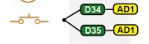
- Inputs-Pushbutton, LDR, Potentiometer
- Outputs-LEDs, OLED Display, Buzzer
- Other- Dual Motor Driver, Li-Ion Charger
- Connectivity- USB, WiFi, Bluetooth


Pinmap

Features
LED
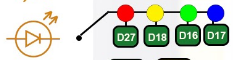
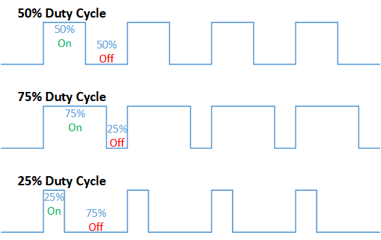
There are four leds on backside of the Magicbit with color red, yellow, green & blue. A LED(light-emitting diode) is a semiconductor light source that emits light when current flows through it. Blinking a LED is the hello world to the microcontroller programming world.
BUTTON
There are two buttons on the front of the Magicbit. The push-button is a component that connects two points in a circuit when you press it. The example turns on an LED when you press the button.
LDR
There is a LDR on the front of the Magicbit. LDR(Light Dependent Resistor) is a light-controlled variable resistor. The resistance of a photo-resistor decreases with increasing incident light intensity. You can measure light intensity using LDR as a analog output.
POTENTIOMETER
The potentiometer is a component with rotating contact that forms an adjustable voltage divider. A potentiometer is a simple knob that provides a variable resistance, which we can read into the Magicbit board as an analog value.
DISPLAY
OLED (Organic Light Emitting Diodes) is a flat light emitting technology. OLED display has a film of organic compound that emits light in response to an electric current.You can display varoius graphics and text on the display.
BUZZER
There is a buzzer on the front of the Magicbit. Buzzer is an electronic device commonly used to produce sound.
BATTERY
There is a Battery connector on the front of the Magicbit.Single cell rechargeable li-ion battery (3.7V) can be plugged in to a battery connector to puwer the Magicbit. Battery can be recharged by providing USb power to the Magicbit.
MODULES
There are four module connectors on the edge connector of the Magicbit, which we refer to as ports. Which can connect various accessories to Magicbit board and program to work with Magicbit. Matching accessory pin connector color marked on the Magicbit. As an example module with blue pin connector should plug in to blue port of the Magicbit.
USB
There is a micro USB port on the back of the Magicbit.Connect the micro USB port to a mobile phone charger or computer through a cable and it will draw power required for the board to function and it also used program magibit and data transferring with a computer.
WiFi
WiFi is a technology that uses radio waves to provide network connectivity. Magicbit consists with wifi module. WiFi technology has widely spread lately and you can get connected almost anywhere; at home, at work, in libraries, schools, airports, hotels and even in some restaurants enabling IOT connectivity capabilities.
BLUETOOTH
Bluetooth is a wireless technology standard used for exchanging data between fixed and mobile devices over short distances using short-wavelength UHF radio waves. Magicbit consists with wifi module which enables IOT connectivity capabilities
EXPANSION HEADER
Magicbit can connect various electronic sensors, electronically controlled actuators,etc to Magicbit via these external connectors
CROCODILE CLIP
Magicbit crocodile clip connectors used to connect an electrical cable to a battery or some other component. Functioning much like a spring-loaded clothespin, the clip’s tapered, serrated jaws are forced together by a spring to grip an object
RESET BUTTON
In electronics and technology, a reset button is a button that can reset a device. On Magicbit, the reset button restarts the Magicbit’s programme
Getting Started

The open-source Arduino Software (IDE) makes it easy to write code and upload it to the board. It runs on Windows, Mac OS X, and Linux. The environment is written in Java and based on Processing and other open-source software.Arduino IDE is not only used for programme Arduino boards but also other development boards like esp32, magicbita dn so on. Let’s get some general idea about Arduino IDE preview. Below picture shows the startup preview of the Arduino IDE. In this at the middle you have your text editor and at the top left side there is a menu bar which have several options

Let’s look at options in the Arduino menu bar.
- File- As the name suggests you can do the documentary things with this option. You can open new sketch, close, save that sketch, open existing sketch or example sketch and change system preferences.
- Edit- With this you can change your font size, indentations and some writing options
- Sketch- This is important as compilation, uploading and library options are available in this.
- Tools- Hardware setup is done in this option. You can change the board type, programmer type and connecting port name with this and configure other hardware settings.
- Help- This option is used for connecting with Arduino references and getting help.
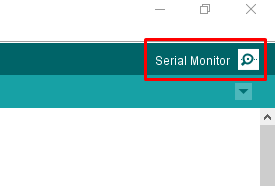
Below the menu bar you have some shortcut keys (command keys). First one is verify key button. By using this you can know your code is grammarly correct or not according to programming language rules. Using the upload button you can do both the compile and upload process at same time. The right top corner have serial monitor icon. This is very important option. This is used to communicate between Arduino IDE and your development board. You can send data to and watch the data which is sent by the development board from this. Under the serial monitor icon we can see some small icon options. This option is used to set the configurations of the new tabs and existing tabs. At the bottom side you can see the debugging console. This shows the result of the compilation and uploading and some other messages which are very useful for debugging.
In the text editor space we can write any Arduino program. This is our playground. We can write any related code in that space. Here are two sections. One is void setup and the other one is void loop. In the void setup we write which we want to execute at the start and one time. So we write pin configurations and other library configurations in the void setup. Our main algorithm is in the void loop. As its name suggests the processor execute this loop section repeatedly at every time. So we write the things which we want to execute at every time in this section. After writing the code go to tools->select your board type and select your port name correctly. Then click the upload button to upload the code.
Learn more about Arduino <https://www.arduino.cc/en/main/software>
Magicbit is based on ESP32 and Arduino core for the Magicbit forked from the espressif/arduino-esp32
Installation Instructions
- Relase Link -https://github.com/Magicbitlk/arduino-esp32/releases/download/V1.0.0/package_Magicbit_index.json
- Install the current upstream Arduino IDE at the 1.8 level or later. The current version is at the [Arduino website](http://www.arduino.cc/en/main/software).
- Start Arduino and open Preferences window.
- Enter one of the release links above into Additional Board Manager URLs field. You can add multiple URLs, separating them with commas.
- Open Boards Manager from Tools > Board menu and install Magicbit platform (and don’t forget to - - select Magicbit from Tools > Board menu after installation).
Powering Up
Magicbit can be powerup by either connecting USB cable or connecting battery. For programming USB cable must be connected to the computer. For the first time powering up Magicbit self test program will be running on the Magicbit and you can see the features available and functional tests on Magicbit display.
To check whether drivers are correctly installed open the Ardunio IDE and go the Tools menu. There should be a port (Eg:COM1) shown when plugging Magicbit to the computer as shown below. If not please follow Installation drivers section.

Installation Drivers (Optional)
Magicbit has CH340 chip as USB-Serial converter which driver already packaged with Ardunio IDE. If port not shown in the Arduino as shown below please install driver
First Project
- Open Ardunio IDE if not opened already.
- Select Magicbit from Tools->Boards
- Select port Tools->Ports
- Open Blink Example File->Examples->Basic->Blink
- Upload the code to the Magicbit using upload button on Arduino IDE
- If Green Led on backside of the Magicbit is blinking your have just begun the magic with Magicbit
Warning
To use analogWrite, Tone and Servo funtions,Include ESP32Servo Sketch->Include Library->ESP32Servo or put #include <ESP32Servo.h> on top of arduino sketch.
Examples
Example 1: Blinking an LED
Introduction
In this example you are learning how to turn on and off a LED or any other actuator which can be controlled by a digital output such as relay, bulb, motor.
Learning Outcomes
From this example, you’ll get an understanding about,
- Pin Mode
- Digital Write
- Delay Functions
Components
- Magicbit
Theory
A digital output allows you to control a voltage with an electronic device. If the device instructs the output to be high, the output will produce a voltage (generally about 5 or 3.3 volts). If the device instructs the output to be low, it is connected to ground and produces no voltage.Here Magicbit is the device and output voltage is either 3.3V for HIGH and 0V for LOW.
Methodology
Magicbit equipped with four onboard leds in Magicbit development board, Lets select yellow LED (which is wired to D18)
By setting output state to high of LED pin will turn on the led and by setting output state to LOW will turn of LED.
Coding
void setup(){
   pinMode(18,OUTPUT);
}
void loop(){
   digitalWrite(18,HIGH);
   delay(1000);
   digitalWrite(18,LOW);
   delay(1000);
}
Explanation
pinMode(pin, Mode): Configures the specified pin to behave either as an input or an output. Here we use pin as an output
digitalWrite(pin No, State): Write a HIGH or a LOW value to a digital pin.Pin mode must be setup for the same pin in Setup to work this function properly.
delay(ms): Pauses the program for the amount of time (in milliseconds) specified as parameter.(note 1000 milliseconds equals to one second)
Note: Write code for a knight rider pattern using on board leds of Magicbit
Example 2: Reading the state of a push button
Introduction
In this example you are learning how read a digital input from something like a button & use it to turn on and off a LED or any other digital device.
Learning Outcomes
From this example, you’ll get an understanding about,
- Digital Read
- IF-ELSE conditions
- Variables
Components
- Magicbit
Theory
A digital input allows you to read digital signals. Microcontroller recognizes the signal as 1(HIGH) when the signal is close to 3.3v (or 5v depending on the microcontroller) and recognizes as 0(LOW) when the signal is close to 0v. This reading can be used in the program to do various things.
Methodology
Magicbit equipped with two onboard push buttons in Magicbit development board, Lets select the push button which is wired to D34. Buttons on the board are in pulled up internally (to learn more about pullups/pulldowns follow this link), which means when button is not pressed the status of the button is 1(HIGH), & when the button is pressed the status of the button is 0(LOW).
Also like in previous example we need to select an LED to indicate the change, lets select RED LED which is wired to pin D27.
First we set the input output configurations of the Button and the LED using pinMode, in this case button is an INPUT, LED is an OUTPUT. Then in the loop section we check the state of the button & store it in an int type variable called buttonState (follow this link to learn more about data types in arduino).
Then we can use the variable as the condition of the if block, and if the button is pressed, the bulb should turn on, and the button is not pressed the light should turn off.
Coding
void Setup(){
   pinMode(27,OUTPUT);
   pinMode(34,INPUT);
}
void loop(){

 int buttonState = digitalRead(34);
 if(buttonState == LOW){
   digitalWrite(27, HIGH);
 }else{
   digitalWrite(27, LOW);
 }
}
Explanation
digitalRead(pin No): Reads the condition of the given pin and returns a digital value HIGH or LOW.
IF/ELSE: Used to evaluate a digital condition, we can put a digital logic condition in then parenthesis. If the condition is true, it executes the code block in the immediate curly bracket section, if the condition is false it executes the code block in the else curly bracket.
- if(condition){
- //Do if condition is true
- }else{
- //Do if condition is false}
Note: Write a code to toggle an LED in the button press. LED turns on when button pressed & released, LED turns off when button is pressed & released again. (Hint: Make use of variables to ‘remember’ the state of the button press).
Example 3: Reading an Analog Signal
Introduction
In this example you are learning to read an analog sensor & print it on the serial console.
Components
- Magicbit
Theory
In real world most of the signals we encounter are analog signals (temperature, air pressure, velocity), they are continuous. But computers work on digital domain, to interact between the worlds, representing an analog signal in the digital domain is important. (to read more about analog to digital conversation, follow this link)
Methodology
For this example we use the potentiometer on the Magicbit board, which is connected to pin, D39. It generates a voltage between 0 and 3.3V according to the angle of the potentiometer.
We read the analog signal and storing it in an int type variable(0v= 0 analog value, 3.3v = 1024 analog value), sensorValue, later, we use this value to print on the serial window of arduino IDE as well as light up the red LED(D27) if the analog value exceeds than 512.
Coding
void setup(){
     pinMode(39,INPUT);
     pinMode(27,OUTPUT)
     Serial.begin(9600);
}
void loop(){
     int sensorValue = analogRead(39);
     Serial.println(sensorValue);

     if(sensorValue > 512){
        digitalWrite(27,HIGH);
     }else{
        digitalWrite(27,LOW);
     }
 }
Explanation
analogRead(pin No): this reads and assigns the corresponding analog value to the left.
Activity
Note: Do the same example using the LDR on the board (D36)
Example 4: Working with Analog Write
Introduction
In this example you are learning how to turn on and off a LED or any other actuator which can be controlled by a digital output such as relay, bulb, motor.
Learning Outcomes
From this example, you’ll get an understanding about,
- Pulse Width Modulation
- Analog Write
Components
- Magicbit
Theory
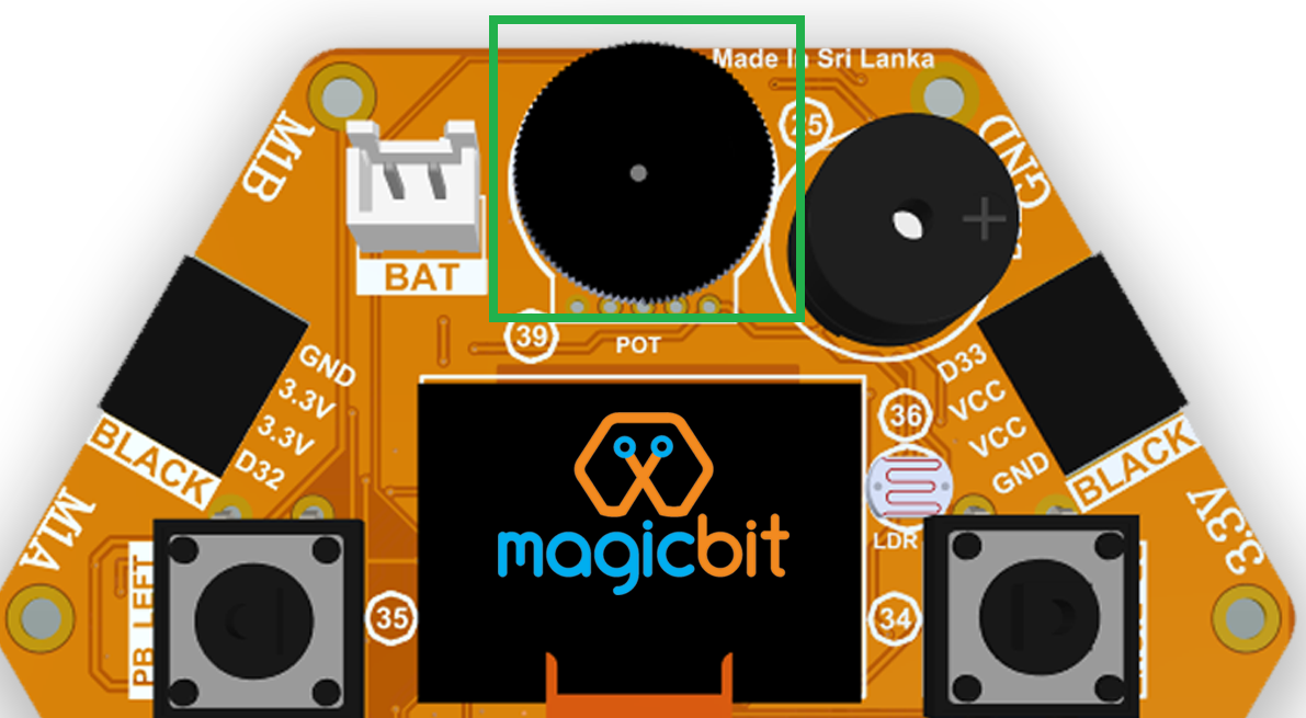
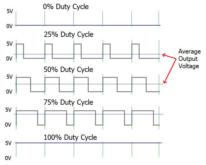
To change the brightness of a LED we could change the voltage the LED is supplied with, but in a microcontroller, ability to change the voltage (converting a digital number to an analog voltage) is limited, so a method called PWM (Pulse Width Modulation) is used. What this does is pulsing on and off the pin in a high frequency. The length of the pulses creates the perception of brightness.
Duty cycle is a term used to describe the ratio between on and off times.
In this example higher Duty cycle gives higher brightness & lower duty cycle gives lower brightness.
Methodology
Lets select green LED (which is wired to D16). We will use a for loop to generate the duty cycle (0 - 0% duty, 255-100% duty). And also to generate 255 cycles.
Coding
#include <ESP32Servo.h>

void setup(){
      pinMode(16,OUTPUT);
}
void loop(){
      for(int i = 0; i < 256; i++){
      analogWrite(16, i);
      delay(10);
}
Explanation
for(int i=0; i<256; i++): There are 3 parameters in a for loop, first parameter we are defining a variable to store the value generated by the for loop. Second parameter specifies the condition that needs to be true to run the for loop(else it breaks out from the loop), third parameter specifies the change happens to the variable in each cycle, in this case 1, added to i.
analogWrite(pin number, pwm value): You can input the pin number you need to do pwm and then the pwm value you need to give to that pin. This assigns the corresponding duty cycle to the pin.
Note This example we have coded to increase the brightness, write a code to do the opposite of that, to fade the brightness of the led, & put both effects together to create a beautiful fade & light up effect.
Example 5: Using Serial Protocol
Introduction
In this example you are learning to use serial communication function.
Learning Outcomes
From this example, you’ll get an understanding about,
- Serial Protocol usage between Magicbit & the PC
Components
- Magicbit
- Computer with arduino installed
Theory
In microcontroller programming, communication between devices is essential. There are hundreds of protocols available, but most common & easy to use is Serial Protocol. Commonly used to communicate information between a microcontroller and a computer.
Methodology
We configure a button as the 2nd example (D34 is used). Then we initialize serial communication between the computer and Magicbit. After that in the loop section if condition check if the button is pressed. If pressed, it prints “Button Pressed” on the serial console.
You could use the serial monitor window of arduino IDE to view the serial output
Then the serial console appears (you have to select the serial port number correctly, follow this link to learn how to).
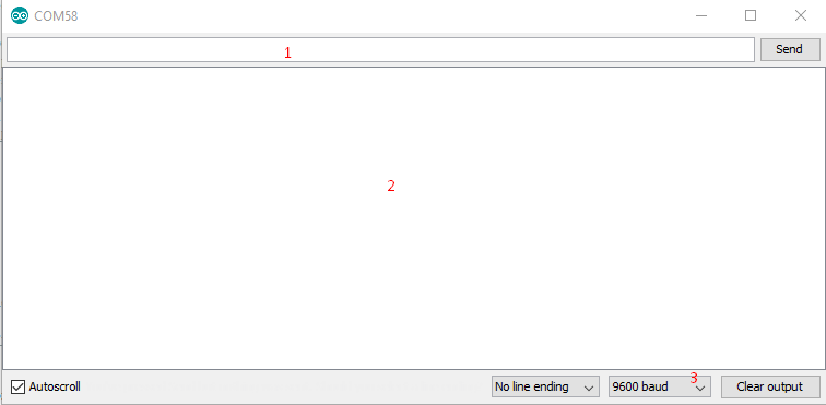
1: You can type in stuff here & hit enter to send data to Magicbit
2: This area shows the data coming from Magicbit
3: From this menu you have to select a common baudrate between the computer and the magic bit.
Coding
void setup(){
  pinMode(34,INPUT);
  Serial.begin(9600);
}
void loop(){
  if(digitalRead(34) == LOW){
    Serial.println(“Button is Pressed”);
  }
}
Explanation
Serial.begin(baudrate): Initializes a serial connection, baudrate specifies the speed of data transfer (bits per second). Standard values are 1200, 2400, 4800, 9600, 14400, 19200, 38400, 57600, 115200, 128000 and 25600
Serial.print(stuff to print): Using this function, serial data can be sent, stuff to print can be any type of arduino variable, or even a static string.
Serial.println(stuff to print): Using this function, serial data can be sent, stuff to print can be any type of arduino variable, or even a static string, this is different than Serial.print() is this always prints the content in a new line, rather than printing all in one line.
Activity
Note: do the same example using Serial.print(), observe the difference. Create a button press counter, which displays the button press count on the serial console of arduino IDE.
Example 6: Using the onboard OLED Screen
Introduction
Color OLED screen on Magicbit can display text as well as simple logos & images.
Learning Outcomes
From this example, you’ll get an understanding about,
- Using Adafruit OLED library
Components
- Magicbit
Theory
Magicbit has a 0.96” OLED Screen which can be communicated with from I2C protocol. The display has the address, 0x3c.
Methodology
Adafruit OLED library(Adafruit_SSD1306 & Adafruit_GFX) is used to handle the LCD, its important to install those libraries beforehand. First we create the content we need to print onto the screen and then use display.display command to update the screen.
Coding
#include <Wire.h>
#include <Adafruit_GFX.h>
#include <Adafruit_SSD1306.h>
#define OLED_RESET 4

Adafruit_SSD1306 display(128,64);

void setup(){
  display.begin(SSD1306_SWITCHCAPVCC, 0x3C);
  display.display();
  delay(3000);
}


void loop(){
  display.clearDisplay();
  display.setTextSize(2);
  display.setTextColor(WHITE);
  display.setCursor(10, 0);
  display.println("Hello");

  display.setTextColor(WHITE);
  display.setTextSize(1);
  display.setCursor(0, 25);
  display.println("Welcome to");
  display.println();
  display.println("Magic");
  display.println("Bit");
  display.display();
  display.clearDisplay();

  delay(1000);

  }
Explanation
display.clearDisplay(): Clears the OLED display.
display.setTextSize(2): Set the font size of the text.
display.setCursor(0, 25): Sets the cursor(determines where the next text will appear).
display.println(stuff to print): print the data given on a new line, similar effect like Serial.println.
display.setTextColor(WHITE): Sets the color of the text.
display.display(): Updates the changes to the screen.
Note:: Make a program to display the ADC value of the potentiometer on the OLED display.
Example 7: DC motor controlling
7.1 Introduction
There are many projects where we have to use motors for many purposes. All processors work under 5V or 3.3V. So their outputs are not enough to supply larger current and voltages to control motors. In this case we use an additional module to control motors. That is a motor driver. As the name suggests, every motor driver is doing the same thing. That is , controlling motors using external power sources based on microcontroller signals. These controlling signals are not constant voltage values. They are PWM(Pulse width modulation) signals. These signals are digital signals. Lot of motor drivers use the H-Bridge mechanism to control the motors. If you use an Arduino board you have to use an external motor driver to control motors. But in the Magicbit you don’t want to buy any external motor controllers. Because it already has an inbuilt H-bridge motor driver. So you can directly connect motors to the Magicbit and you can play with them.
Learning outcomes:
- Using inbuilt motor driver to control motors
- Apply motor controlling process for projects
7.2 Components
- Magicbit
- brushed DC motors(3V or 6V)
7.3 Theory
First let’s look at how this whole process is happening. We all know about that every motor needs power source to work. So if you bought 3v motor you have to supply 3V for proper working. The passing current through the motor is depend on torque of the motor. If motor axel is working freely then it gets low amount of current. If motors are in difficult condition to rotate there axel then it gets higher amount of current. To control motors we used voltage sources. Voltage sources are sources which supply any amount of current under constant voltage. So the speed of motors will depend on the voltages. If we supply high voltage then motor will work at higher RPM and vice versa. Therefore now you can understand that we can control the speed by controlling the supply voltage level. But this is an old way and it’s not efficient and accurate. Modernly we use PWM pulses. PWM means pulse width modulation. In this case we generate a square wave with some constant frequency to control the motors. So the lower state of this wave is nearly zero volt (0V) and the higher state of the wave is nearly supply voltage. Therefore we are able to use our full supply voltage to control the motors. But how can we control the motor speeds using this theorem. That is very easy. If we consider one cycle (duty cycle) of the wave that includes two parts. One is the High stage part and the other one is Low stage part. Let’s say High stage time duration is T1, Low stage Time duration is T2 and one cycle time duration is T. So we can simply write the equation below.
T=T1+T2
If T2=0 and T=T1,then there isn’t any lower state part in every cycle. In this case motor is working with full speed. Because we always give source voltage to motor. But if T1=0 and T=T2, there is no supply voltage and current to the motor. In this case motor is fully turned off. So the speed will be zero. Let’s look at another situation. Lets say T1=T2 ,then T1=T2=T/2. So at this time both time periods of high and low states are equal to every cycle. Now the average value of the wave is half of the source power. Therefore the supply voltage to the motor is half of the main supply voltage(we don’t know the variation between the supply voltage and the motor speed. because it depends on your motor.therefore we can’t say the motor speed will be half of the maximum speed under half of supply voltage). In this way we can get every voltage between 0 and source voltage from average voltage by changing the ratio between T1 and T2. To measure the PWM signal average, we use some factor value called duty cycle value. This value is a percentage value of the ratio of T1 and T.
Duty cycle=(T1/T)x100%
In the microcontrollers we represent this duty cycle value from bit value. If we use 8 bits then we can get 0-255 range to represent duty cycle. In that case 255 means 100% duty cycle and 0 means 0% duty cycle and so on. Now you have some general idea about motor control signals. These PWM signals are not limit to motor controlling applications. These signals are used for many purposes. Next look at how can we use this theorem to motor controlling process. To control motors we use a microcontroller to generate PWM signals. As the introduction describes, these voltage ranges and current of the PWM signals are not sufficient to control the motors. So we used motor driver for that purpose. All we know is that motors can rotate in two opposite directions with various speeds. Because of that reason we get two outputs from the microcontroller to control motor. If we want to rotate the motor in one direction then we use one output to generate a PWM signal while the other one is in low state. If we want that motor rotates in the opposite direction, in that case we use a second output pin to generate a PWM signal while setting the low state to the first pin. Because of the lack of current and voltage of this pin outputs, we will use motor controller unit. This unit includes an H-bridge switching mechanism. Let’s look at how it works. Before moving to that part, take a look at what transistor is. Transistor is a semiconductor device which is used to control signals. There are a lot of transistor types. But every transistor works in the same principle. A transistor has three pins. One pin is used to supply the signal. These signals can be voltage or current signals. The source current is going through other pins. According to the input signal this flowing current is changing. If input signal is larger than some defined value then the passing current will be maximized and if input signal is lower than some amount, then the passing current will be nearly neglectable. So these 2 situations are known as cutoff and saturation regions of the transistor. At these stages the transistor works as a switch. So if we connect microcontroller output into the transistor input signal, then at the high digital signal transistor will be on and at the low digital signal transistor will be off. Now you have a basic idea about transistor mechanisms.
So now let’s look at the H-bridge mechanism.
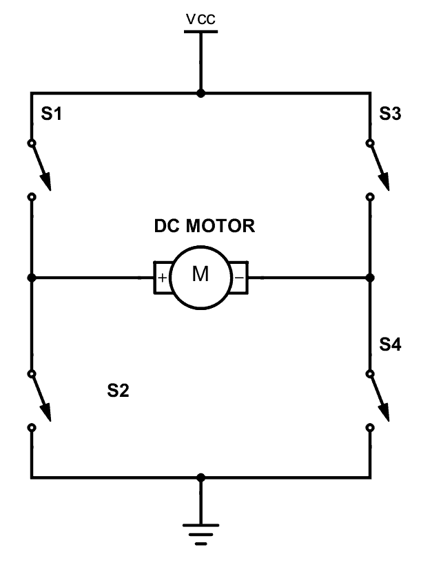
As you can see there are four switches s1, s2, s3 and s4. These switches are actually transistors or some switching component. Let’s analyse this diagram. If s1 and s4 are ON and others are OFF then, the motor will work in one direction. By changing the ON and OFF time of the S1 and S4 with some constant frequencies, we can rotate that motor with various speeds. If s3 and s2 are ON and others are OFF then the motor will go in the other direction. Also we can change the motor speed by changing the ON and OFF time of S2 and S3 switches. If all switches are OFF or all are ON then the motor will stop.
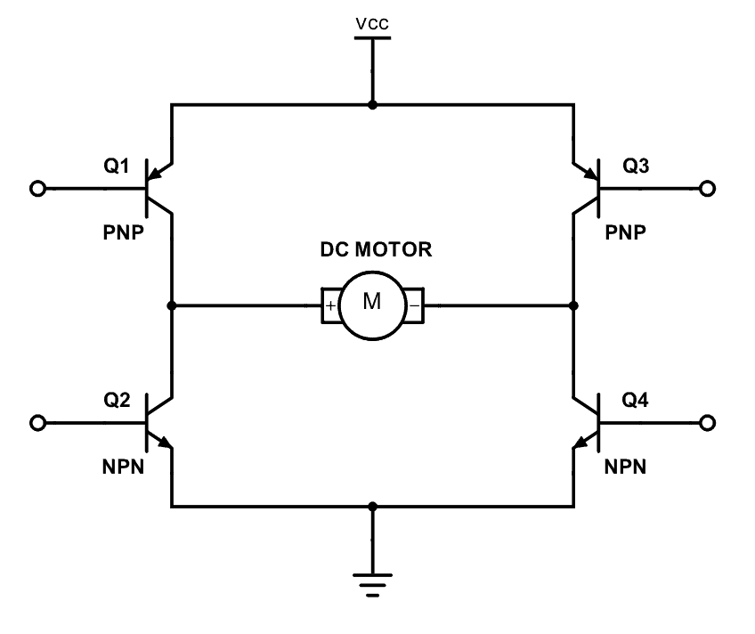
So now you can see how switches are replaced by transistors. Q1, Q2, Q3 and Q4 represents S1, S2, S3 and S4 switches. In this diagram the base pin is the input signal pin of the transistor. If we supply a high state signal to that pin the transistor will saturate and that transistor acts as a closed switch (ON). Otherwise it will act as an open (OFF) switch. In this diagram there are four inputs to control for transistors. But we combine these four inputs to two inputs which satisfy the above switching conditions.
In the Magicbit it includes L110 motor driver IC which has the ability to control two motors. So it is a two channel motor driver IC. It internally connected to the esp32 processor of the Magicbit from four. M1A, M1B, M2A and M2B are the pins of the lower port of the Magicbit which are output pins of the L9110 IC.
7.4 Methodology
Connect the motor to the M1A and M1B or M2A and M2B pins or connect two motors to the port on the left corner in the lower side of the Magicbit. Connect the Magicbit to your PC and upload the following code.
7.5 Coding
#include <ESP32Servo.h>
int M1A = 26; //motor drive input pins
int M1B = 2;
int M2A = 27;
int M2B = 4;
void setup() {
  pinMode(M1A, OUTPUT); //configure as inputs
  pinMode(M1B, OUTPUT);
  pinMode(M2A, OUTPUT);
  pinMode(M2B, OUTPUT);
}
void loop() {
  for (int i = 0; i <= 255; i++) { //rotate both motors to direction
    analogWrite(M1A, i);//pwm signal
    analogWrite(M1B, 0);
    analogWrite(M2A, i);
    analogWrite(M2B, 0);
    delay(100);
  }
  analogWrite(M1A, 255);//stop for 1 second
  analogWrite(M1B, 255);
  analogWrite(M2A, 255);
  analogWrite(M2B, 255);
  delay(1000);
  for (int i = 0; i <= 255; i++) { //rotate both motors to opposite direction
    analogWrite(M1A, 0);
    analogWrite(M1B, i);
    analogWrite(M2A, 0);
    analogWrite(M2B, i);
    delay(100);
  }
  analogWrite(M1A, 255);//stop for 1 second
  analogWrite(M1B, 255);
  analogWrite(M2A, 255);
  analogWrite(M2B, 255);
  delay(1000);
}
.. image:: https://github.com/magicbitlk/Magicbit-Magicblocks.io/blob/master/Images/magic.jpg?raw=true?raw=true
What is Internet of Things
The Internet of things is nothing new. It is an evolutionary next step in the machine to machine communication paradigm. With an ever increasing number of ‘things’ at our disposal the need for connected ‘things’ has grown rapidly. However with increasing options comes added complexity which introduces steep learning curves and more importantly more confusion. What devices should I use? What cloud platform will best server my interest? I am new to IoT where should I start? Those are the question that would linger in any one who would dare to wonder in to the internet of Things. We, at magicblocks.io have put some magic to work to make the life of both the newcomer and the professional one step easier.
Magicblocks.io Introduction
Magicblocks.io is the IoT platform by A&T Labs for building IoT applications with minimal hassle. Tried and tested over the years the lateset release of magicblocks.io will connect to more devices and do more thanks to the open source project Node-Red. magicblocks.io is a launchpad for learning and prototyping your internet of things. It consists of
- Hardware suite made up of
- Development boards
- Prototyping kits for sensors & actuators
- Cloud platform made up of
- Drag and drop editor to easily cook up your solutions
- Dashboards to visualize your data
- Data storage
- API services
Everything has been designed to make the learning curve as shallow as possible for the newcomer and as flexible as possible for the advanced user.
Magicblocks.io Playground
Any ioT creation you want to connect with nodes without any coding and your project running in the cloud platform the development board you use will not have much memory or more processing capability, unless you want to create Image Processing, Character Recognizing, DB Handling, you can create any project on it.
You can also create attractively online dashboards online without any coding
Magicblocks.io Dashboard
In Magicblocks you can also create Web based-dashboards attractively for your IoT designs without any codes. You need to connect the necessary widgets to the dashboard that you want and to configure the settings you need to reach them. Then, you can access your Online Dashboard from the dashboard menu on your dashboard, where you can click on the URL in the browser to access the Dashboard via any Device Device such as Smart Phone, Tablet, PC. Any ioT creation you want to connect with nodes without any coding and your project running in the cloud platform the development board you use will not have much memory or more processing capability, unless you want to create Image Processing, Character Recognizing, DB Handling, you can create any project on it.
You can also create attractively online dashboards online without any coding
Getting Started
Create Magicblocks.io Account
- Go to magicblocks website http://magicblocks.io/
- Select SIGNUP

- Click on the SIGN UP button after inserted your details
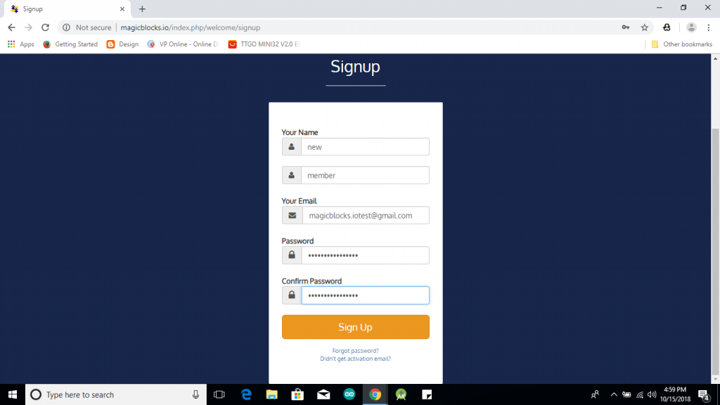
- Go to the email account you provided and activate your Magicblocks account with the Activation Link
- Follow the Activation Link which we have sent you as an email.

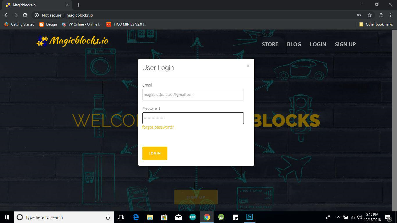
Login to Your Magicblocks.io Account
- Go to Magicblocks.io official website. www.magicblocks.io
- Select LOGIN
- Provide your login details.
- Enter your email address and the Magicblocks Password and sign in to magicblocks
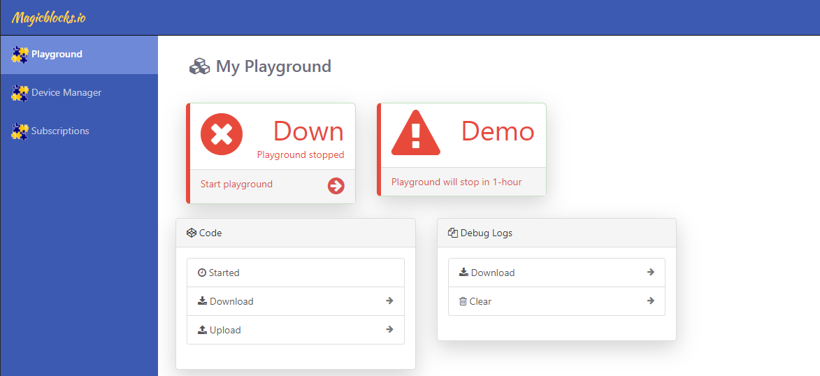
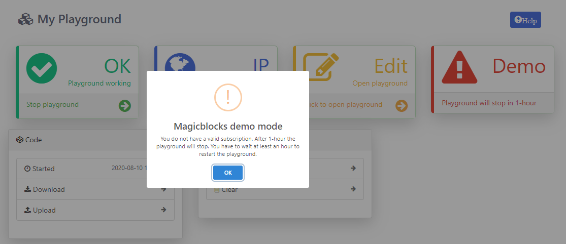
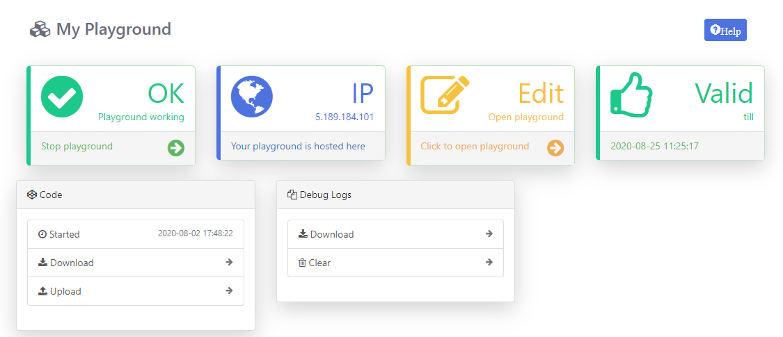
Start the Playground
When you login for the first time your playground will not be running. Playground is the visual programming environment based on Node-Red that has been customized for seamless integration with hardware devices to enable IoT. If you do not have a valid subscription, you will be allowed to run the playground only for 1 hour continuously before it is automatically stopped. You will need to restart the playground manually after this 1 hour period. You can subcribe to 3 months free subscription by enterting coupon code in Subscription tab provided with your magicbit device. If you have any issue please write to info@magicbit.cc
Create a new device
Go to Device Manager and add a new device.. Set device type as Magicbit & set status to Active . You can use any name and description.
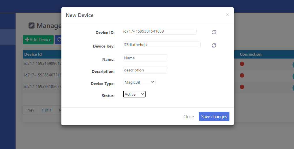
Keep this browser tab open since you will need to copy the device Id and the key to setup the device in the next step.
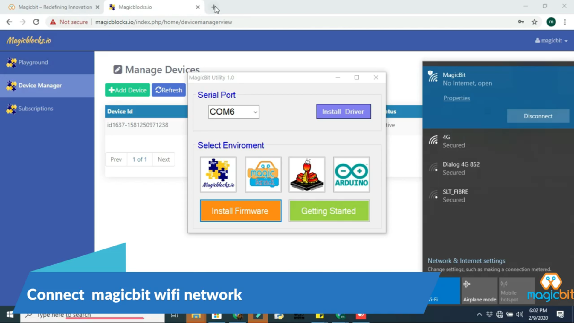
Setting up a device
Connect Magicbit to computer using provided USB cable.
Download Magicbit utility tool and install drivers
Select COM port from drop down list and select magicblocks to install firmware. .. image:: Images/Utility.PNG
- Wait until uploading is completed and search for its configuration WiFi access point to come up. It would be named “Magicbit” in the default configuration
- Connect to this WiFi access point and go to http://192.168.4.1
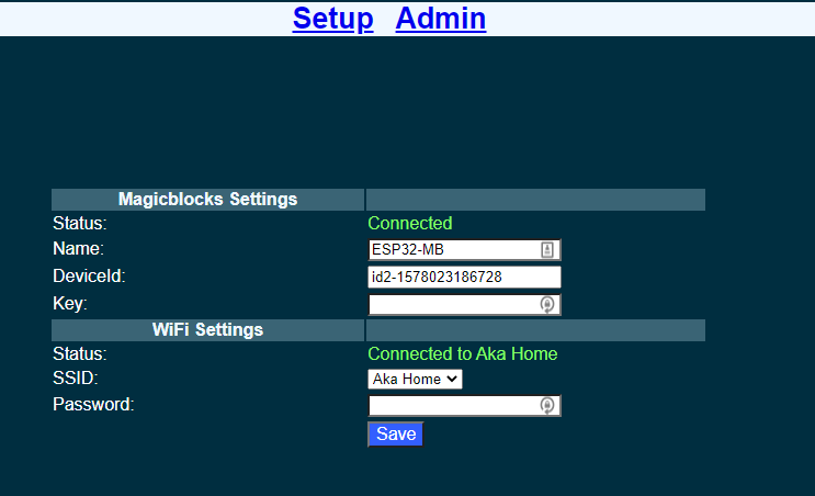
- Fill in the device Id and the key that was generated in the previous step. You can change the Name to any name you like up to 32 characters. Select the WiFi SSID from the drop down and enter the WiFi password. If your WiFi is not listed here make sure the WiFi AP is active and reset the Magicbit board and retry.
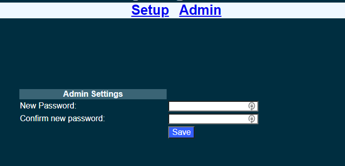
- Save the configuration. The default admin password is 12345. You can change this from the Admin tab
- Once saved, the Magicbit will restart and try to connect to the WiFi and then to magicblocks. You can connect to the Magicbit’s configuration WiFi AP and navigate to http://192.168.4.1 to check the status of the connection.
- Login to magicblocks, navigate to Device Manager and check if the Connection column comes up as a blinking green indicator. If yes, you can proceed to the next step
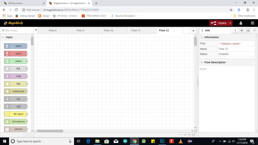
Go to the playground!
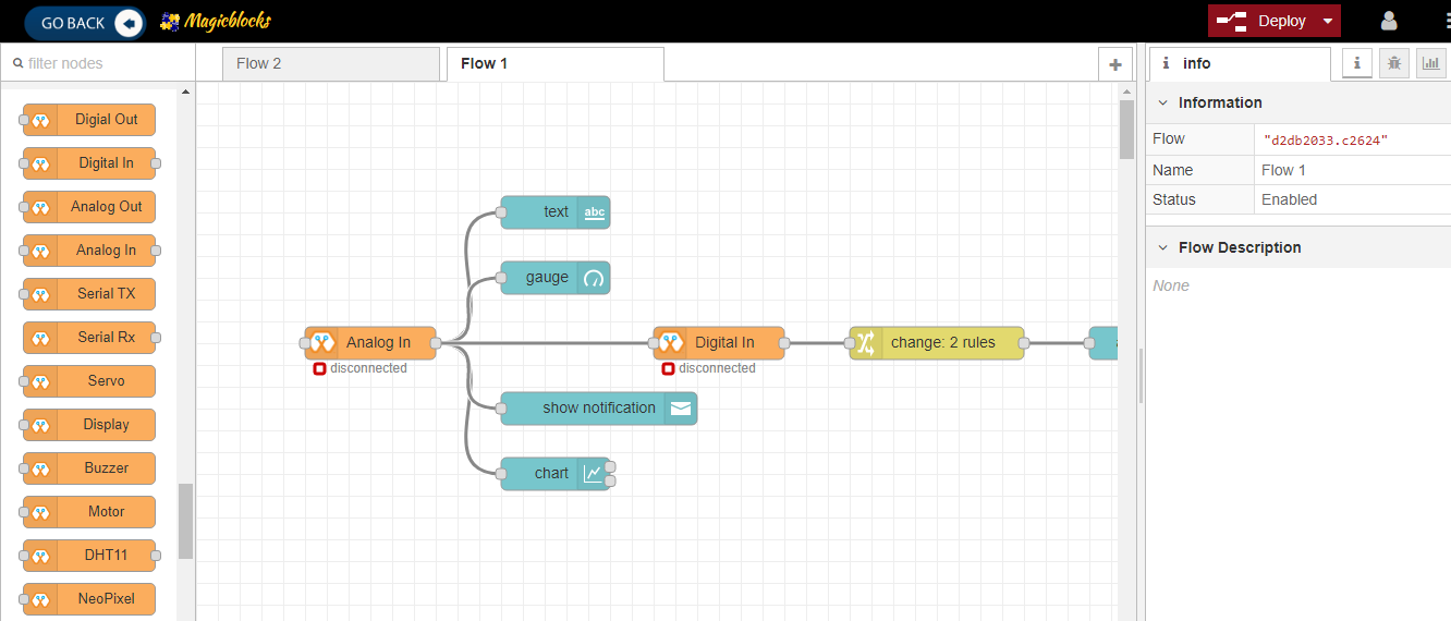
- Login to magicblocks and click on Edit to open the playground.
- The playground is a hosted instance of a customized version of the open source Node-Red application. On the left you will find the palette where all the blocks will reside. You can drag and drop the blocks from the palette to the canvas and start rolling very quickly. Once done click the Deploy button on the top right corner and all your changes will be saved. In the next section we will go through some examples covering all the relevant blocks
Hello Magicbit
Let’s start magic with displaying a text on Magicbit display.
Open the Device Manager in your magicblocks account
- Turn on your Magicbit board that was setup in the previous section and wait for it to connect
- Copy the device Id of this Magicbit board
- Open the playground
- Drag and drop the Display block under the category Magicbit
- Double click on the block and paste the device Id
- Drag and drop an inject blocks under the input category and connect them to the Display block
- In one inject node set payload type as String and type Hello Magicbit in the text box. You can set a topic too.
- Click deploy
- Click button in Inject node to see the magic. You can set any text from any where in the world!!!
Warning
If you are not familiar with Magicblocks or Nodered you can quickly learn essential features from here. https://magicbit-magicblocksio.readthedocs.io/en/latest/#playground
Magicbit Blocks
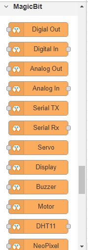
Following Blocks are available.
- Digital Out
- Digital In
- Analog Out/PWM
- Analog In
- Serial Tx
- Serial Rx
- Servo
- Display
- Buzzer
- Motor
- DHT11
- NeoPixel
- Ultrasonic
This block set enables you to control individual pins of the device from the playground. The functionality of each block is described below:
How Configure Blocks
Every block has a property called Device ID where you need to specify to which device this block belongs to. This is important because you will be working with multiple devices in a typical IoT project. You can find device ID from magicblocks device manager.
Digital Out
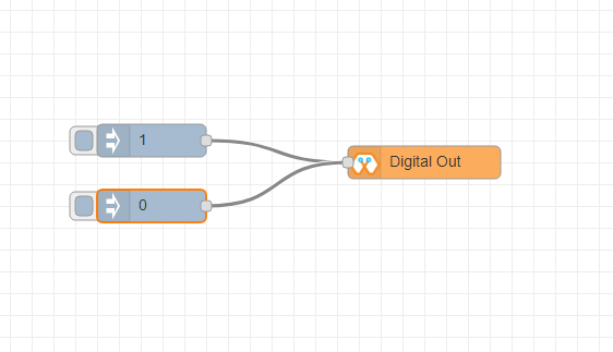
This block is used to set a digital output pin to 1 or 0 based on the input. An input of 1 or true will make the configured pin go HIGH and vice versa
- Configuration
- Pin: pin number of the Digital pin to write to. Available pins can be selected from dropdown list.
- Name: Any name desired
- Input
- value to be written to the pin. Accepts 1 (true) or 0 (false) eg: {“payload”: 1}
Digital In
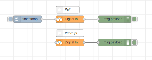
This block will read Input status of a pin. There are two methods to get input 1. Poll - Block need to triggered to get input status. Any input will serve as a trigger. (eg:inject block) 2. Interrupt - If there is any change of pin state of Magicbit block will output the current state Input status can be passed to a another block or viewed on the debug window.
- Configuration:
- Pin: pin number of the digital pin to read .Select from drop down list
- Name: Any name desired
- Method: Poll/Interrupt
- Input
- Any input. Used as a trigger
- Output
- Value of the pin as 1 or 0 in the following format and the pin number as the topic
Analog Out
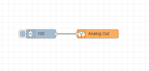
This block used to set PWM to pins of Magicbit. Value should be in range of 0-255. Inject block or output of a another block can be used to set the value.
- Configuration:
- Pin: pin number of the to set PWM. Select from drop down list
- Name: Any name desired
- Input
- Inject block or any block. Input value should be in range of 0-255
Analog In
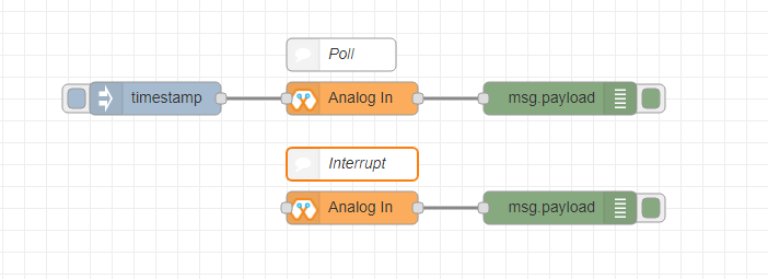
This block will read analog value of the ADC pin of the module. Similar to the digital in block you need to set method to read the value. Any input sent to the block will serve as the trigger.
- Poll - Block need to triggered to get input status. Any input will serve as a trigger. (eg:inject block)
- Interrupt - If there is any change greater or less than threshold value of Magicbit block will output the analog value
- Configuration:
- Pin: pin number of the analog pin to read (Required)
- Name: Any name desired
- Method: Poll/Interrupt
- Threshold: If interrupt method selected value return from output if there is any change greater or less than this value
- Input
- Any input. Used as a trigger
- Output
- Value of the pin from 0 to 4096 (12bit ADC) {“payload”: 965}
Control LED form web dashboard
Introduction
There are 2 main methods of achieving this goal.
- By using Inject Block.
- By using Dashboard Switch.
From both of this methods we discuss about second method .
Methodology
- Setting Up the Switch Block
Drag & drop the Switch block from the dashboard nodes section to the Flow.
_agR2N5xHmh.png?auto=compress%2Cformat&w=740&h=555&fit=max)
Double-click on the Switch node and set up a basic dashboard ui (user- interface) from the drop-down menu and a name for your field. The Mode as number input from the drop-down menu for both On and Off. And set on payload as 1 and off payload as 0.
_pC5mHGJOdF.png?auto=compress%2Cformat&w=740&h=555&fit=max)
- Setting Up the Digital Out Block
Drag & drop the Digital out block from the Magicbit nodes section on the left of the screen to the flow. Double-click on the digital out block and type or paste your unique Device id from the Device Manager Tab on your Magicblocks account. ( This will link the digital out block with your Magicbit )
_zMgUMg4CA9.png?auto=compress%2Cformat&w=740&h=555&fit=max)
- Finally Deploying the Blocks & Using the Dashboard UI to Access It
Connect the Switch block with the Digital Out node. Click on Deploy button on the top right-hand corner of the screen. After deploying go to the dashboard ui by clicking the link to dashboard URL on the top right-hand corner of the screen.
_6UfxCC6pwj.png?auto=compress%2Cformat&w=740&h=555&fit=max)
_4nQryObhwR.png?auto=compress%2Cformat&w=740&h=555&fit=max)
Once in the dashboard you can toggle the switch you just setup on and off to control the LED you assigned to the digital out block.
_hD62lHh6uu.png?auto=compress%2Cformat&w=740&h=555&fit=max)
Copy the your Dashboard URL and this can be accessed via the internet to display text onto your Magicbit Display from anywhere in the World. Note:: make a flow to control all four LED’s of the magicbit at once using web dashboard
Display input parameters on web dashboard
Introduction
In this example we doing that display some data on web dashboard which sent by Magicbit at real time. To achieve this goal we need to feed some signal to magicbit. For this purpose we used two push buttons of magicbit to generate digital signals. The web dashboard display the state of the two buttons.
Methodology
Start and Open the Playground. Next make sure your Magicbit is connected to the internet and plugged-in and also linked to your account through Device Manager. - Setting Up the Digital In Block Drag & drop the Inject block from the input nodes section on the left of the screen to the Flow.
Double-click on the Digital In block and type or paste your unique Device id from the Device Manager Tab on your Magicblocks account. (This will link the digital in with the Magicbit )
_43KFWV7zgn.png?auto=compress%2Cformat&w=740&h=555&fit=max)
_DpO0mgTxcX.png?auto=compress%2Cformat&w=740&h=555&fit=max)
Choose ‘PB Right(34)’ or ‘PB Left(35)’ from the PIN drop-down menu.(Connects with the Right or Left Push Button on your Magicbit)
_0gFNEimAaB.png?auto=compress%2Cformat&w=740&h=555&fit=max)
Select the Method as Interrupt from the drop-down menu
- Setup the Change Block
This Node is used to change the 1 & 0 signal input from the Digital In node to any text you wantDrag & Drop the Change Block from the function nodes section on the left of the screen to the flow.
_Ad58vq13G5.png?auto=compress%2Cformat&w=740&h=555&fit=max)
Add new rule from the ‘+’ Button to use 2 rules
_ZhqXgK19dw.png?auto=compress%2Cformat&w=740&h=555&fit=max)
Change the function of both of the rules from Set to Change from the drop-down menu.

Next change the ‘Search for’ function from String(text) to Number in both of the rules. And make sure the ‘Replace with’ function is set to String(text).

lets Set up the rules.
- The First Rule to search for ‘1’ in signal input and replace it with our text (e.g. ‘Right Button Released’ or ‘Right OFF’)
- The Second Rule to search for ‘0’ in signal input and replace it with our text (e.g. ‘Right Button Pressed’ or ‘Right ON’)
The text ‘Right’ or ‘Left’ depends on the Push Button which is linked to the Digital In Node in the above step.
(image below shows an example of the rules)
_nM5J4AriDy.png?auto=compress%2Cformat&w=740&h=555&fit=max)
- Setup the Text Block
Drag & drop the Text block from the dashboard nodes section to the Flow
_DyGxifBpOo.png?auto=compress%2Cformat&w=740&h=555&fit=max)
Double-click on the text node and set up a basic dashboard ui [user- interface] from the drop-down menu and a name for your field.
_AcZ0DiNtm1.png?auto=compress%2Cformat&w=740&h=555&fit=max)
now Setup the same node configuration for the other Push Button. So Copy & Paste the 3 nodes.
_52OOMz0vPE.png?auto=compress%2Cformat&w=740&h=555&fit=max)
Change the PIN on the Digital In node for the other Push Button. Change the Text in Change node from ‘Right’ to ‘Left’ or vice versa.
- Finally Deploying the Blocks
Make sure all the blocks are connected. Click on Deploy button on the top right-hand corner of the screen. After deploying go to the dashboard ui by clicking the link to dashboard URL on the top right-hand corner of the screen.
_crop_j20qwrEkjH.png?auto=compress%2Cformat&w=740&h=555&fit=max)
Press the Left or Right Push Buttons and the text will be displayed on the Dashboard.
_cTYK9glhGi.png?auto=compress%2Cformat&w=740&h=555&fit=max)
_f2j1lf1swQ.png?auto=compress%2Cformat&w=740&h=555&fit=max)
Playground
The editor window consists of four components:
- The header at the top, containing the deploy button, main menu, and, if user authentication is enabled, the user menu.
- The palette on the left, containing the nodes available to use.
- The main workspace in the middle, where flows are created.
- The sidebar on the right.
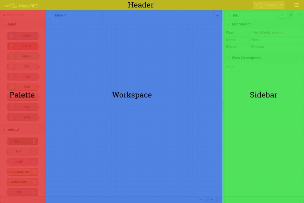
The main workspace is where flows are developed by dragging nodes from the palette and wiring them together. The workspace has a row of tabs along the top; one for each flow and any subflows that have been opened.
Flow

Adding a flow
To add a new flow, click the .. image:: https://github.com/magicbitlk/Magicbit-Magicblocks.io/blob/master/Images/plus.png?raw=true
button in the top bar.
Editing flow properties
To edit a flow’s properties, double-click on its tab in the top bar. This will open the Flow Properties dialog.
Within the dialog, the flow’s name and description can be set. The description can use Markdown syntax for formatting and will appear in the Information sidebar.
The Status property can be used to disable or enable the flow.
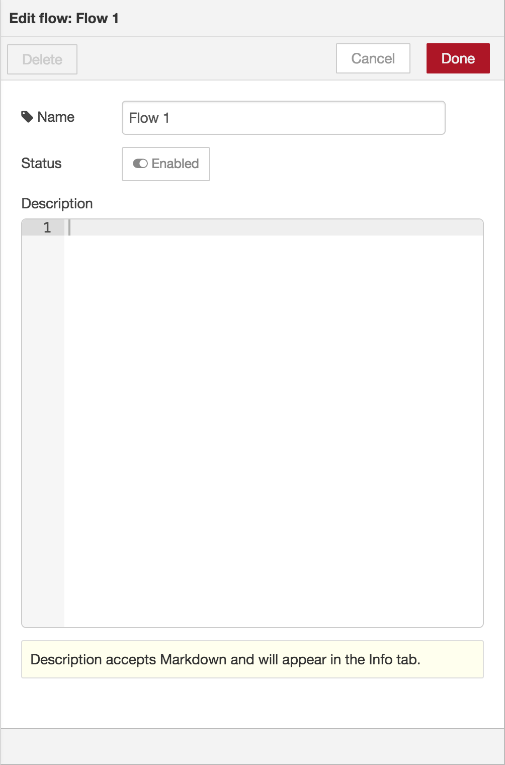
Deleting a flow
To delete a flow, click the ‘Delete’ button in the Flow Properties dialog.
Nodes
Nodes can be added to the workspace by either:
- Dragging them from the palette
- Using the quick-add dialog
- Importing from the library or clipboard
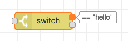
Nodes are joined together by wires via their ports. A node can have at most one input port and many output ports. A port may have a label that is displayed when the mouse hovers over it. A node may specify labels, for example, the Switch node shows the rule that matches the port. The labels can also be customised in the node edit dialog.
Some nodes display a status message and icon below the node. This is used to indicate the runtime state of the node - for example, the MQTT nodes indicate if they are currently connected or not.
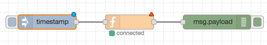
If a node has any undeployed changes, it displays a blue circle above it. If there are errors with its configuration, it displays a red triangle.
Some nodes include a button on either its left or right edge. These allow some interaction with the node from within the editor. The Inject and Debug nodes are the only core nodes that have buttons.
Editing node configuration
A node’s configuration can be edited by double clicking on the node, or pressing Enter when the workspace has focus. If multiple nodes are selected, the _first_ node in the selection will be edited.
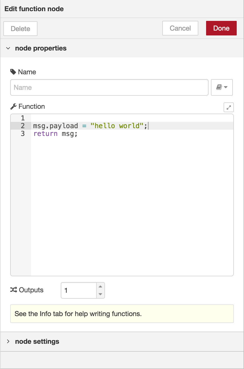
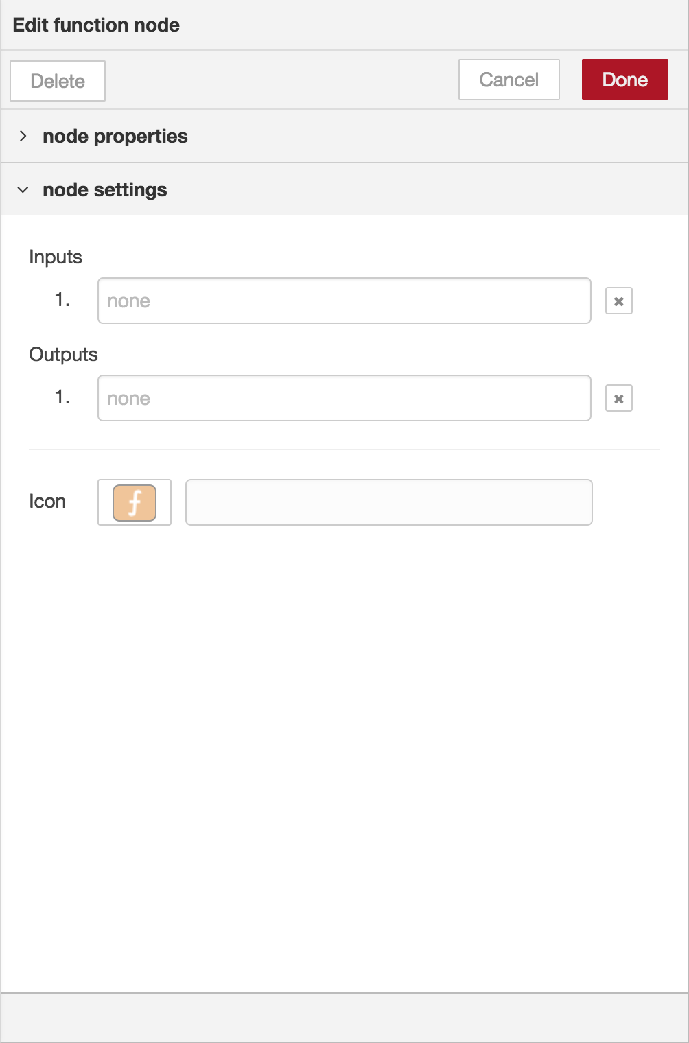
The node edit dialog has two separate sections; properties and settings. The properties section shows the edit form specific to the node type being edited. The settings section shows the common settings that can be set on all nodes. This includes the custom port labels as well as the icon for the node.
Clicking on the icon shows the Node icon picker that can be used to select the icon for the node from the list of all available icons.
Configuration nodes
A Configuration (config) Node is a special type of node that holds reusable configuration that can be shared by regular nodes in a flow.
For example, the MQTT In and Out nodes use an MQTT Broker config node to represent a shared connection to an MQTT broker.
Configuration nodes are added through the edit dialog of a node that requires the config node. It will have a field to select from the available config nodes of the required type or to add a new instance. .. image:: https://github.com/magicbitlk/Magicbit-Magicblocks.io/blob/master/Images/editor-edit-node-config-node.png?raw=true
Clicking the button next to the select box will open the edit dialog for the selected node, or add a new instance.
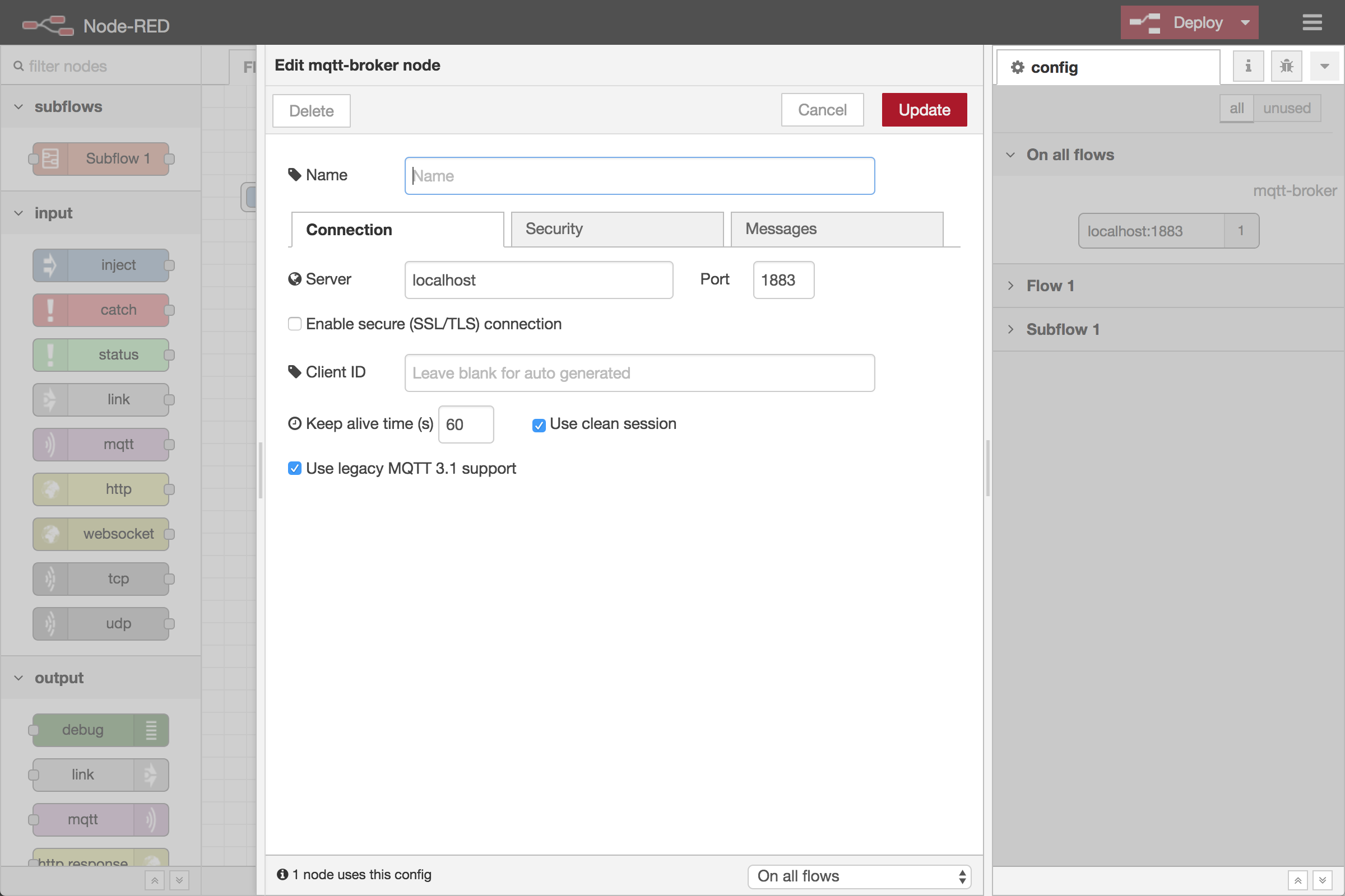
The config node edit dialog only has the node properties section - as a config node has no icon or ports to set labels on.
In the footer of the dialog is an indication of how many nodes use this config node. It also provides a select box to set the scope of the config node. The scope determines which flows the config node is available on. By default it is available on all flows, but the select box can be used to make it local to just one flow.
The Configuration Nodes Sidebar can be used to manage all config nodes.
Wires
Nodes are wired together by pressing the left-mouse button on a node’s port, dragging to the destination node and releasing the mouse button.
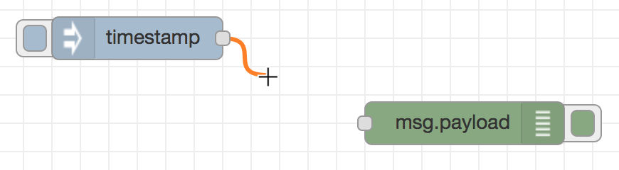
Alternatively, if the Ctrl/Command key is held down, the left-mouse button can be clicked (and released) on a node’s port and then clicked on the destination. If the Ctrl/Command key remains held and the just-wired destination node has an output port, a new wire is started from that port. This allows a set of nodes to be quickly wired together.
This can also be combined with the Quick-Add dialog that is triggered by a Ctrl/Command-Click on the workspace to quickly insert new nodes and have them already wired to previous nodes in the flow.
Splitting wires
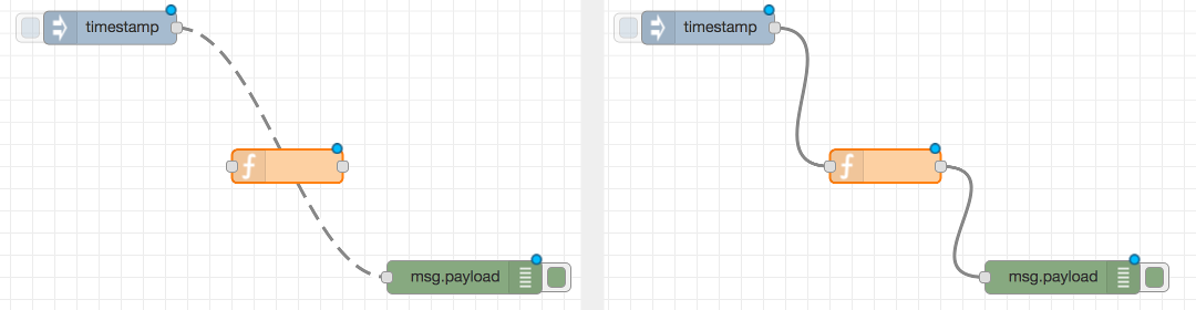
If a node with both an input and output port is dragged over the mid-point of a wire, the wire is draw with a dash. If the node is then dropped, it is automatically inserted into the flow at that point.
Moving wires
To disconnect a wire from a port, select the wire by clicking on it, then press and hold the Shift key when the left-mouse button is pressed on the port. When the mouse is then dragged, the wire disconnects from the port and can be dropped on another port. If the mouse button is released over the workspace, the wire is deleted.
If a port has multiple wires connected to it, if none of them is selected when button is pressed with the Shift key held, all of the wires will move.
Deleting wires
To delete a wire, first select it by clicking on it and then press the delete key.
Selection
A node is selected when it is clicked on. This will deselect anything currently selected. The Information Sidebar will update to show the node’s properties and help text for its type.
If the Ctrl or Command key is held when clicking on the node, the node will be added to the current selection (or removed if it was already selected).
If the Shift key is held when clicking on the node, it will select that node and all other nodes it is connected to.
A wire is selected when it is clicked on. Unlike nodes, it is only possible to select one wire at a time.
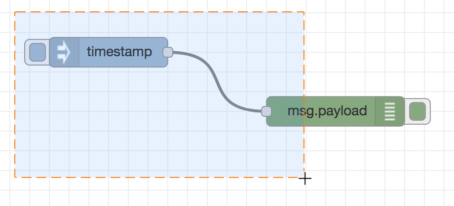
Lasso Tool
The lasso tool can be used to select multiple nodes. It is enabled by click-dragging on the workspace.
It cannot be used to select a wire.
Selecting all nodes
To select all nodes on the current flow, ensure the workspace has focus and then press Ctrl/Command-a.
Editor clipboard
The editor supports the standard copy/cut/paste actions. Note they use an internal clipboard rather than the system clipboard.
Import & Export
Flows can be imported and exported from the editor using their JSON format, making it very easy to share flows with others.
Importing flows
To import a flow, open the Import dialog, paste in the flow json and click ‘Import’.
The ‘Import’ button will only be active if valid JSON is pasted into the dialog.
The dialog also offers the option to import the nodes into the current flow, or to create a new flow for them.

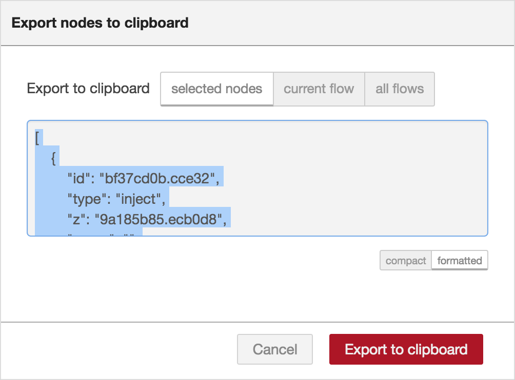
Exporting flows
The Export dialog can be used to copy flow json out of the editor.
It can export either the selected nodes, the current flow (including its tab node) or the complete flow configuration.
It offers the option to export compact or formatted JSON. The compact option generates a single line of JSON with no whitespace. The formatted JSON option is formatted over multiple lines with full indentation - which can be easier to read.
Dashboards
What is Magicblocks Dashboard?
Magicblocks Dashboard is a module that provides a set of nodes in Magicblocks to quickly create a live data dashboard.
Since Magicblocks is based on NODE-RED opensource platform you can learn more about dashboard using following links
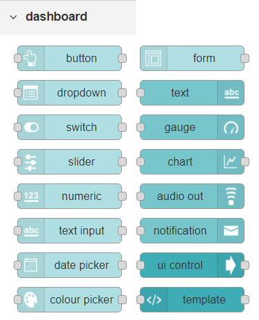
Nodes from the dashboard section provide widgets that show up in your application user interface (UI).
The user interface is organized in tabs and groups. Tabs are different pages on your user interface, like several tabs in a browser. Inside each tab you have groups that divide the tabs in different sections so that you can organize your widgets.
Every widget should have an associated group that determines where the widget should appear on the user interface.
To create a tab and a group follow the following instructions (see figure below):
- On top right corner of the Magicblocks window you have a tab called dashboard.
- Select that tab (1). To add a tab to the user interface click on the +tab button (2).
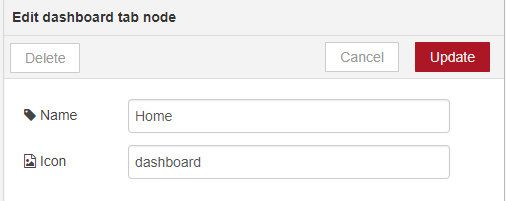
- Once created, you can edit the tab by clicking on the edit button (3)
You can edit the tab’s name and change its icon
- Name: you can call it whatever you want
- Icon: you should use a name accordingly to the icon’s names in this link: https://klarsys.github.io/angular-material-icons
- After creating a tab, you can create several groups under that tab. You need to create at least one group to add your widgets. To add a group to the created tab, you need to click on the +group button (4).
- Then, you can edit the created group by clicking on the edit button (5).

- You can edit its name, select its corresponding tab and change its width.
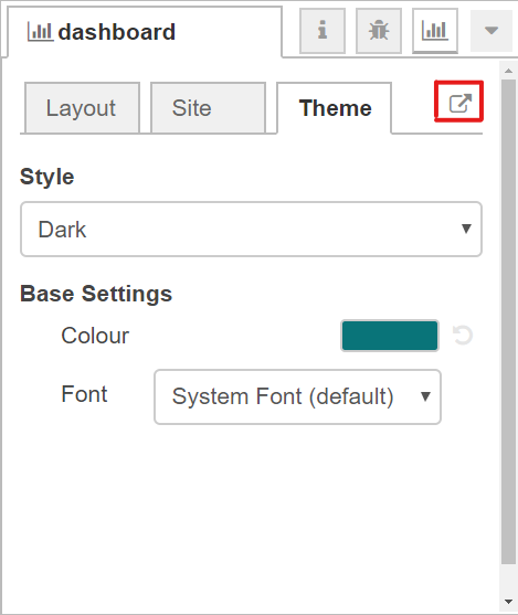
Dashboard Theme
The Magicblocks Dashboard has a white background and a light blue bar by default. You can edit its colors in the Theme tab on the up right corner as show in the following figure.
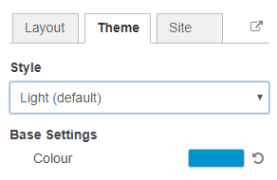
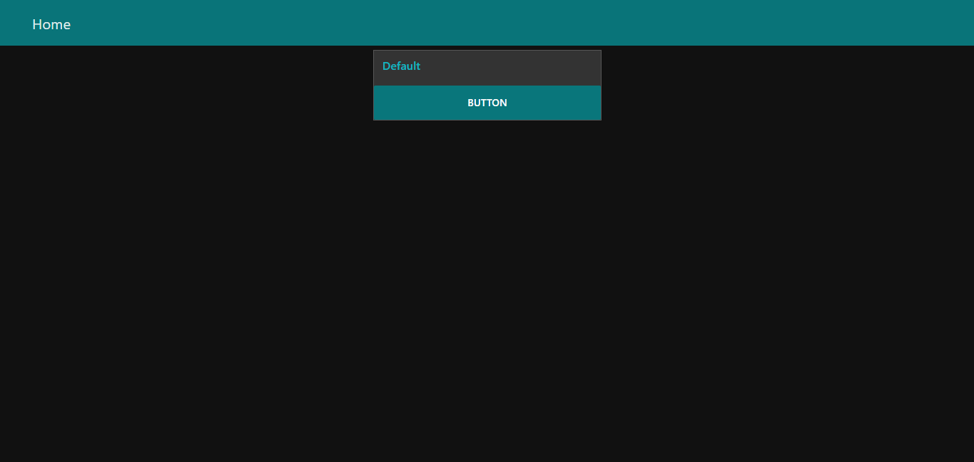
- Change the style, deploy the changes and see the Dashboard UI changing its colors. For example, like in the following figure
Dashboard Site
At the right upper corner of the Magicblocks window, you have another tab called Site that allows you to do further customization as show in the figure below.
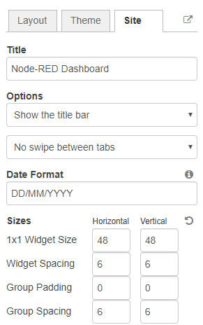
Feel free to change the settings, then deploy the changes and see how the UI looks. At the moment you won’t see much difference because you haven’t added anything to the dashboard yet. Those changes will be noticeable when you start adding widgets to the UI.
Creating a User Interface – Example
In this section we’re going to make a dashboard example to show you how you can build and edit your own dashboard – we won’t actually add functionalities to the widgets – we’ll do that in future projects. This dashboard will have the following features
- Two different tabs: one called Room and another called Garden
- The Room tab will have two groups and the Garden tab will have one group
- We’ll add a color picker and a switch to the room groups
- We’ll add a chart to the Garden group
Creating the Tabs
On the top right corner on the Magicblocks window, select the dashboard tab and create two new tabs by clicking on the +tab button.
Edit one tab with the following properties
- Name: Room
- Icon: tv
And the other one with the following
- Name: Garden
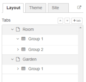
- Icon: local_florist
Then, add two groups to the Room tab and one group to the Garden tab. The following figure shows how your dashboard layout looks.
Adding the Widgets
Add a switch, a slider, a colour picker and a gauge to the flow as show in the following figure .. image:: https://github.com/magicbitlk/Magicbit-Magicblocks.io/blob/master/Images/flow.png?raw=true
Double click on the switch. A new window pops up.
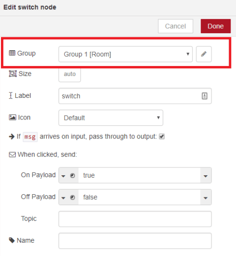
In this new window you can choose where you want your button widget to appear. In this case we want it to appear in the Room tab, Group 1 as highlighted in red in the previous figure.
Then, do the same for the other widgets but add them to the following groups:
- slider: Group 1 [Room]
- color picker: Group 2 [Room]
- gauge: Group 1 [Garden]
Source: (https://randomnerdtutorials.com/getting-started-with-node-red-dashboard/)
Core Blocks
The Magicblocks palette includes a default set of nodes that are the basic building blocks for creating flows. This page highlights the core set you should know about.
All nodes include documentation you can see in the Info sidebar tab when you select a node.
- Inject
- Debug
- Function
- Change
- Switch
- Template
Inject node
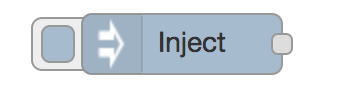
The Inject node can be used to manual trigger a flow by clicking the node’s button within the editor. It can also be used to automatically trigger flows at regular intervals.
The message sent by the Inject node can have its payload and topic properties set.
The payload can be set to a variety of different types:
- a flow or global context property value
- a String, number, boolean, Buffer or Object
- a Timestamp in milliseconds since January 1st, 1970
Debug node
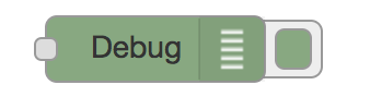
The Debug node can be used to display messages in the Debug sidebar within the editor.
The sidebar provides a structured view of the messages it is sent, making it easier to explore the message.
Alongside each message, the debug sidebar includes information about the time the message was received and which Debug node sent it. Clicking on the source node id will reveal that node within the workspace.
The button on the node can be used to enable or disable its output. It is recommended to disable or remove any Debug nodes that are not being used.
The node can also be configured to send all messages to the runtime log, or to send short (32 characters) to the status text under the debug node.
The page on Working with messages gives more information about using the Debug sidebar.
Function node
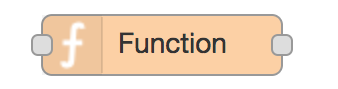
The Function node allows JavaScript code to be run against the messages that are passed through it.
A complete guide for using the Function node is available here .
Change node
The Change node can be used to modify a message’s properties and set context properties without having to resort to a Function node.
Each node can be configured with multiple operations that are applied in order. The available operations are:
- Set - set a property. The value can be a variety of different types, or can be taken from an existing message or context property.
- Change - search and replace parts of a message property.
- Move - move or rename a property.
- Delete - delete a property.
- When setting a property, the value can also be the result of a JSONata expression. JSONata is a declarative query and transformation language for JSON data.
Switch node
The Switch node allows messages to be routed to different branches of a flow by evaluating a set of rules against each message.
The node is configured with the property to test - which can be either a message property or a context property.
There are four types of rule:
- Value rules are evaluated against the configured property
- Sequence rules can be used on message sequences, such as those generated by the Split node
- A JSONata Expression can be provided that will be evaluated against the whole message and will match if the expression returns a _true_ value.
- An Otherwise rule can be used to match if none of the preceding rules have matched.
The node will route a message to all outputs corresponding to matching rules. But it can also be configured to stop evaluating rules when it finds one that matches.